
This deck was bought in Germany and the seller didn't take care packing it and the result was a D.O.A. reel to reel machine which capstan motor didn't work.
Thanks to the people of the reeltoreel Yahoo! group list I was tracing the problem from the capstan motor itself back to the current flow direction.
After a visual inspection all pieces seemed to be in good shape, so the first thing done was to check a big capacitor and the capstan motor itself.
To do this, the wires needed to be unsoldered/cut from the rest of the circuit and then, measure the impedance between some wires that must be:
Between pink and red: ca. 130 Ohms
Between pink and brown: ca. 180 Ohms
Between green and grey: ca. 360 Ohms
Between green and yellow: 370 Ohms
The values measured were:
Pink - red = 126,9 (instead of 130)
Pink - brown = 174,8 (instead of 180)
Green - grey = 350 (instead of 360)
Green - yellow = 352 (instead of 370)
Thanks to the people of the reeltoreel Yahoo! group list I was tracing the problem from the capstan motor itself back to the current flow direction.
After a visual inspection all pieces seemed to be in good shape, so the first thing done was to check a big capacitor and the capstan motor itself.
To do this, the wires needed to be unsoldered/cut from the rest of the circuit and then, measure the impedance between some wires that must be:
Between pink and red: ca. 130 Ohms
Between pink and brown: ca. 180 Ohms
Between green and grey: ca. 360 Ohms
Between green and yellow: 370 Ohms
The values measured were:
Pink - red = 126,9 (instead of 130)
Pink - brown = 174,8 (instead of 180)
Green - grey = 350 (instead of 360)
Green - yellow = 352 (instead of 370)
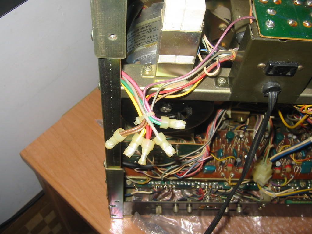
According to measured values, the capstan motor was in good shape. Next step was to go down to a small board with the number TD-2087. It contains only six blue spark killers.
After unsoldering the six spark killers and measured them, all seemed to be fine. So... what's happen?!.
Frank Oomen was helping me directly by email and pointed me to the next step: the speed switch selector. In a first time I thought that this couldn't be the problem because I had sprayed lot of contact cleaner in it, but as the problem could be anywhere, I unsoldered the speed switch and opened it.
Putting the wires together as if the switch were working well, the motor run, so the problem was finally located in the speed switch.
I did several fixes to it to try to repair it, but each time I closed it and soldered the six wires and tested the deck during some time, it finally always with a misswork. I decided to bypass this switch and set the deck in its high speed (7.5 ips / 19 cms) and go on with more tests.
The first thing I noticed was that the rec bulb was blown and the dolby/S.O.S one too. Measuring with a tester the current there was 24 V DC. The rec bulb could be replaced with a led and a resistor put in serie, but the dolby / S.O.S. bulb couldn't be replaced with a led because it originally is inside a socket with small lateral windows, so when the dolby button was pressed, its small lateral window was inline with the bulb's socket lateral window and the light passed inside it. The same ocurred with the S.O.S. button.
A led always lights to the front direction, not to the sides. As the space in the socket was narrow, I couldn't use two leds (one lighting in each direction, directly to the small windows).
The solution was to replace the original bulb with smaller bulbs. As the ones I had here were 6.3 V, I put four in serial so that the 24V current were OK with them.
Ater soldering the bulbs I tested the deck and after a few time, it didn't sound neither the meters readed anything.
I didn't understand what was happening here. Measuring the current here, instead of the original 24V DC, now there only were 1.2 V DC.
I unsoldered the four bulbs thinking that maybe some shortcut had happened, but all wires were OK and even then, the voltage was about 1.2V DC in that line, which was the same that powered the sound boards.
From the power suppy to that point, there was a socket that could be unplugged. With the socket unplugged, the voltage at this point were right, but as soon as I reconnected it again, it dropped down again.
In a first place I thought that the problem must be located in the audio board. The current flow was:
From the socket to the record board
From the record board to the playback board
All connections here between boards were done with wires soldered between them, so to try to find the problem I unsoldered all the wired from the record board to the playback board to test if the voltage then was OK or not.
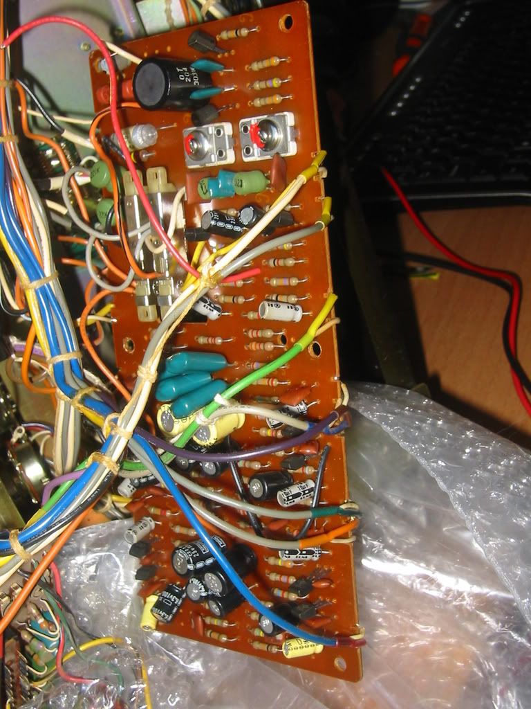
To work better and with more space, I soldered a longer wires from the inside of the deck to the outside of it so that I could place the record board in a more confortable place to work.
Checking here, the voltage was nearly to zero. Well, I said to myself that the problem must be located then in this board, but visually nothing seemed to be in bad shape.
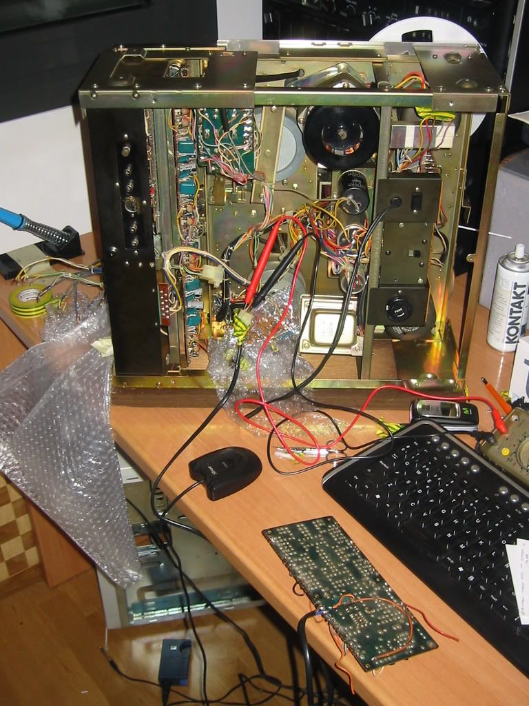
Anyway, I replaced all electrolitic caps with new ones and tested all transistors. All measured well. I looked for some broken track or some shortcut. Spent lot of hours here, even unsoldered most of the resistors and measured them. All seemed to be in good shape.

When I was decided to stop the work, I measured again in the incomming power supply with the boards unplugged, and the voltage was OK, but as soon as I plugged there anything to that power supply, the voltage were nearly zero, even if I plugged there the four bulbs and no more.
Well, never thought that the problem could be the incomming power. It always dropped to nearly zero when anything was connected to it. Checking the previous components, there were just a simple circuit to convert the AC power into a DC power.
After some hours studying the components, I found a zener diode blown, and a transistor in bad shape (2SC1013). The zener diode was a 24V and about 1W.
Looking for a possible replacement for the original transistor, I had a 2SD837, that had better and bigger values, so I decided to try it. After turn the deck on, the zener diode was blown again.
In a first moment I thought that maybe I had connected something wrong, so I tried another zener diode. Ocurred the same, always got it burned, and after three tries, the transistor was fried.
I ordered new parts and as a replacement for the 2SC1013, choose a 2SD1980, which I thought could be a better replacement (10 watts or max. power disipation againts 7 watts of the original one, and the gain, better that the original).
When I soldered this transistor and a new zener diode... always something were fried.
The rest of the components of the circuit were OK, so I tried to study the board and thought that maybe the problem were in the pin out of the transistors, and looking at the datasheet of the new transistor, the pin out was different from the original transistor.
Well, some fried elements later, I soldered new pieces and took care of the pin out of this transistor (the base and collector are interchanged). Crossed the fingers and turned the deck on. ¡¡¡It worked!!!.
Spent some hours putting all things and soldering wires to its original places and got the deck running and playing music. But still the problem of the speed switch.
Finally I used the power switch to be used in the place of the original speed switch, and had to make a fix with the actuator because the speed actuator if larger than the power on/off actuator, but it worked.
To replace then the power on/off switch I used another one from a parts cassette deck. That wasn't the same type, but could adapt it to work in its new place.
All seemed to be then solved, so I checked the rest of the things. Do you think that all was already fixed?. No. If had a wire unsoldered from the erase head and the heads needed to be demagnetized a few times and all switched cleaned to get clear sound.
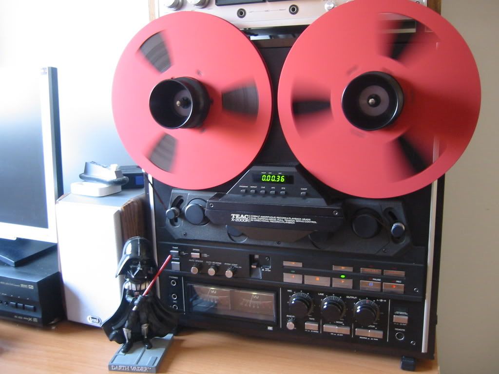
But after looooots of hours on it, now this deck is in a perfect shape to be used again during the next years.
This morning I made a video of the Akai GX-600DB making company to the rest of my second setup. Hope you enjoy.
After unsoldering the six spark killers and measured them, all seemed to be fine. So... what's happen?!.
Frank Oomen was helping me directly by email and pointed me to the next step: the speed switch selector. In a first time I thought that this couldn't be the problem because I had sprayed lot of contact cleaner in it, but as the problem could be anywhere, I unsoldered the speed switch and opened it.
Putting the wires together as if the switch were working well, the motor run, so the problem was finally located in the speed switch.
I did several fixes to it to try to repair it, but each time I closed it and soldered the six wires and tested the deck during some time, it finally always with a misswork. I decided to bypass this switch and set the deck in its high speed (7.5 ips / 19 cms) and go on with more tests.
The first thing I noticed was that the rec bulb was blown and the dolby/S.O.S one too. Measuring with a tester the current there was 24 V DC. The rec bulb could be replaced with a led and a resistor put in serie, but the dolby / S.O.S. bulb couldn't be replaced with a led because it originally is inside a socket with small lateral windows, so when the dolby button was pressed, its small lateral window was inline with the bulb's socket lateral window and the light passed inside it. The same ocurred with the S.O.S. button.
A led always lights to the front direction, not to the sides. As the space in the socket was narrow, I couldn't use two leds (one lighting in each direction, directly to the small windows).
The solution was to replace the original bulb with smaller bulbs. As the ones I had here were 6.3 V, I put four in serial so that the 24V current were OK with them.
Ater soldering the bulbs I tested the deck and after a few time, it didn't sound neither the meters readed anything.
I didn't understand what was happening here. Measuring the current here, instead of the original 24V DC, now there only were 1.2 V DC.
I unsoldered the four bulbs thinking that maybe some shortcut had happened, but all wires were OK and even then, the voltage was about 1.2V DC in that line, which was the same that powered the sound boards.
From the power suppy to that point, there was a socket that could be unplugged. With the socket unplugged, the voltage at this point were right, but as soon as I reconnected it again, it dropped down again.
In a first place I thought that the problem must be located in the audio board. The current flow was:
From the socket to the record board
From the record board to the playback board
All connections here between boards were done with wires soldered between them, so to try to find the problem I unsoldered all the wired from the record board to the playback board to test if the voltage then was OK or not.
To work better and with more space, I soldered a longer wires from the inside of the deck to the outside of it so that I could place the record board in a more confortable place to work.
Checking here, the voltage was nearly to zero. Well, I said to myself that the problem must be located then in this board, but visually nothing seemed to be in bad shape.
Anyway, I replaced all electrolitic caps with new ones and tested all transistors. All measured well. I looked for some broken track or some shortcut. Spent lot of hours here, even unsoldered most of the resistors and measured them. All seemed to be in good shape.
When I was decided to stop the work, I measured again in the incomming power supply with the boards unplugged, and the voltage was OK, but as soon as I plugged there anything to that power supply, the voltage were nearly zero, even if I plugged there the four bulbs and no more.
Well, never thought that the problem could be the incomming power. It always dropped to nearly zero when anything was connected to it. Checking the previous components, there were just a simple circuit to convert the AC power into a DC power.
After some hours studying the components, I found a zener diode blown, and a transistor in bad shape (2SC1013). The zener diode was a 24V and about 1W.
Looking for a possible replacement for the original transistor, I had a 2SD837, that had better and bigger values, so I decided to try it. After turn the deck on, the zener diode was blown again.
In a first moment I thought that maybe I had connected something wrong, so I tried another zener diode. Ocurred the same, always got it burned, and after three tries, the transistor was fried.
I ordered new parts and as a replacement for the 2SC1013, choose a 2SD1980, which I thought could be a better replacement (10 watts or max. power disipation againts 7 watts of the original one, and the gain, better that the original).
When I soldered this transistor and a new zener diode... always something were fried.
The rest of the components of the circuit were OK, so I tried to study the board and thought that maybe the problem were in the pin out of the transistors, and looking at the datasheet of the new transistor, the pin out was different from the original transistor.
Well, some fried elements later, I soldered new pieces and took care of the pin out of this transistor (the base and collector are interchanged). Crossed the fingers and turned the deck on. ¡¡¡It worked!!!.
Spent some hours putting all things and soldering wires to its original places and got the deck running and playing music. But still the problem of the speed switch.
Finally I used the power switch to be used in the place of the original speed switch, and had to make a fix with the actuator because the speed actuator if larger than the power on/off actuator, but it worked.
To replace then the power on/off switch I used another one from a parts cassette deck. That wasn't the same type, but could adapt it to work in its new place.
All seemed to be then solved, so I checked the rest of the things. Do you think that all was already fixed?. No. If had a wire unsoldered from the erase head and the heads needed to be demagnetized a few times and all switched cleaned to get clear sound.
But after looooots of hours on it, now this deck is in a perfect shape to be used again during the next years.
This morning I made a video of the Akai GX-600DB making company to the rest of my second setup. Hope you enjoy.






 Posts
Posts

