
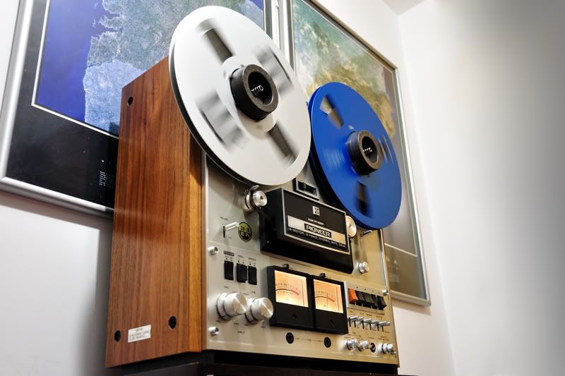
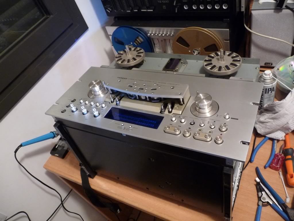
After change the capstan belt I shot this short video showing the Pioneer RT-1020H playing back the "Ghost In The Shell 2: Innocence" OST recorder hot at 19 cm/s (7.5 ips) on a Basf LP35 tape.
Saturday, January 1, 2011

Saturday, November 20, 2010
REP: Changing the Pioneer RT-1020H capstan belt
Easy, very easy. You won't need more than 15 minutes in most cases.
Tools needed:
- A new belt, of course
- Philips screwdriver
- Lithium grease
Steps:
0- Unplug the deck.
1- Remove the top-back panel. Just unscrew the philips screws where noted:
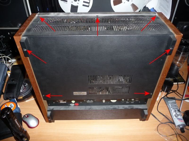
2- Be aware to remove the metal silver piece in the top-front of the deck before removing the entire back panel.
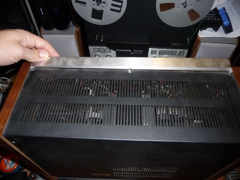
3- Remove the entire back panel.
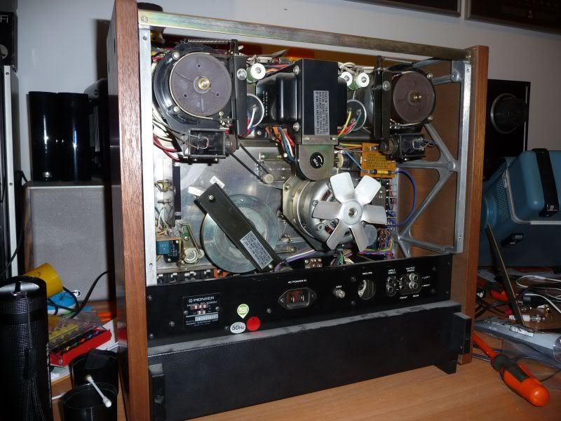
4- Remove the capstan wheel piece retainer showed in the previous pic. It only has two philips screws, but be aware, both have washers, so don't miss them!
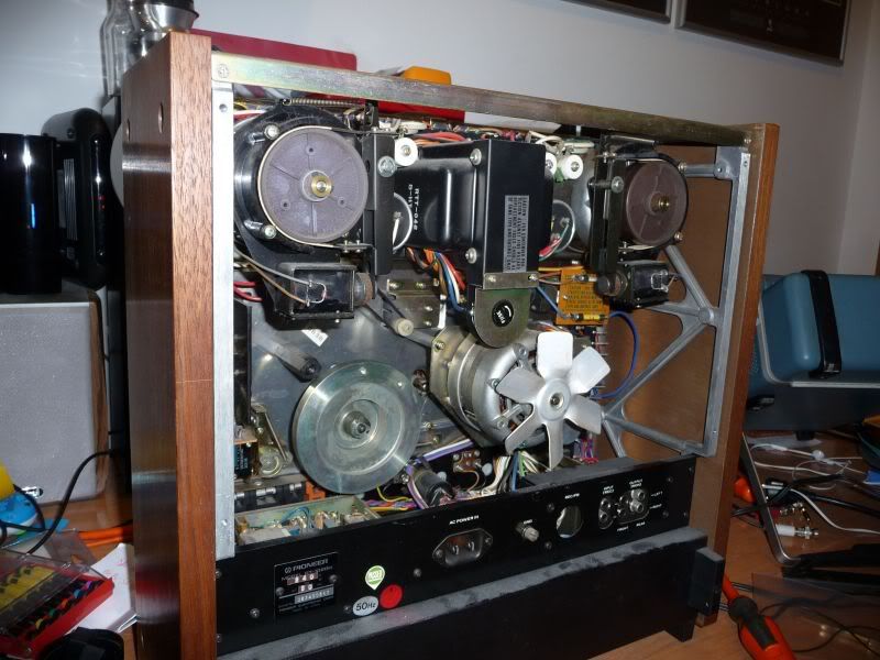
5- Now you can put the belt "easily". First of all you need to know that the capstan motor pulley has two ways: one for 50 Hz and one for 60 Hz. The 50 Hz is the inner and the 60 Hz is the outer (from the motor). So take the belt with your hand and with some hability, try to put it in the motor pulley from the back. This is the hardest point, so don't worry if you can't do it in the first try.
Doesn't matter if you put the belt in the incorrect motor pulley way in this step. The goal is to put it in the motor pulley.
6- Gently pull the belt to the capstan fly wheel zone and put it around the wheel. The belt must be placed in the inner part of it.
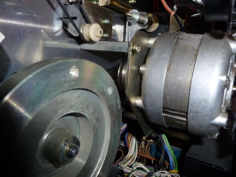
7- Ok, with the belt just replaced you need to be sure about which of the two motor pulley ways must it be placed. From your point of view, the closest to the motor would be for 50 Hz and the other for 60 Hz. To change it just use your fingers of a hand while the other hand rotates the capstan fly wheel.
8- Now the belt is in the correct place, so you must place the capstan wheel piece retainer back to its place. Remember, two screws and each with a washer, but previous to do it would be a good idea to place a bit of lithium grease in the contact zona of the fly wheel with this retainer.
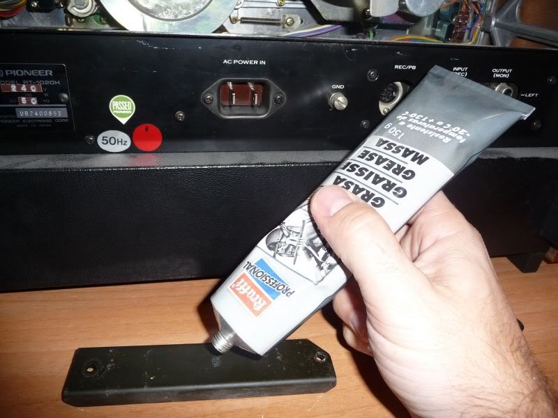
9- The final step is the place the back panel to its original place taking in mind to place the metal silver piece in the top-front before, and over it, the panel and screw!
10- Test the job
Tools needed:
- A new belt, of course
- Philips screwdriver
- Lithium grease
Steps:
0- Unplug the deck.
1- Remove the top-back panel. Just unscrew the philips screws where noted:
2- Be aware to remove the metal silver piece in the top-front of the deck before removing the entire back panel.
3- Remove the entire back panel.
4- Remove the capstan wheel piece retainer showed in the previous pic. It only has two philips screws, but be aware, both have washers, so don't miss them!
5- Now you can put the belt "easily". First of all you need to know that the capstan motor pulley has two ways: one for 50 Hz and one for 60 Hz. The 50 Hz is the inner and the 60 Hz is the outer (from the motor). So take the belt with your hand and with some hability, try to put it in the motor pulley from the back. This is the hardest point, so don't worry if you can't do it in the first try.
Doesn't matter if you put the belt in the incorrect motor pulley way in this step. The goal is to put it in the motor pulley.
6- Gently pull the belt to the capstan fly wheel zone and put it around the wheel. The belt must be placed in the inner part of it.
7- Ok, with the belt just replaced you need to be sure about which of the two motor pulley ways must it be placed. From your point of view, the closest to the motor would be for 50 Hz and the other for 60 Hz. To change it just use your fingers of a hand while the other hand rotates the capstan fly wheel.
8- Now the belt is in the correct place, so you must place the capstan wheel piece retainer back to its place. Remember, two screws and each with a washer, but previous to do it would be a good idea to place a bit of lithium grease in the contact zona of the fly wheel with this retainer.
9- The final step is the place the back panel to its original place taking in mind to place the metal silver piece in the top-front before, and over it, the panel and screw!
10- Test the job
Friday, December 25, 2009


Monday, July 20, 2009
REP: Calibrating Pioneer RT-909 torgue
I calibrated the tension and backtension of a Pioneer RT-909 some months ago but I didn't remember that I had uploaded two videos about it.
The first shows the problem, only present in RWD mode:
This can be produced by you if you just play with the internal pots without knowing exactly what are you doing and without having the correct tools to calibrate the tension:
- The service manual where is described the procedure to follow and the order in which is needed to do it.
- A spring gauge, or even better, a tentelometer.
Notice that even when the tension is not correct in one transport function and rest seems to work OK, all the entire calibration is needed because the values of the rest impact in the other tensions.
This is the result after some time calibrating the pots until getting the correct readings in the tentelometer:
The first shows the problem, only present in RWD mode:
This can be produced by you if you just play with the internal pots without knowing exactly what are you doing and without having the correct tools to calibrate the tension:
- The service manual where is described the procedure to follow and the order in which is needed to do it.
- A spring gauge, or even better, a tentelometer.
Notice that even when the tension is not correct in one transport function and rest seems to work OK, all the entire calibration is needed because the values of the rest impact in the other tensions.
This is the result after some time calibrating the pots until getting the correct readings in the tentelometer:
Friday, July 17, 2009


Saturday, July 4, 2009
AN: Photographies
I know that in the last weeks I didn't update the blog, but I've been busy with lot of work during week and most of the remaining time has been spent in my hobbies. Also here is very very hot and sunny, during the day it's 30 ºC (measured in shadow) and my home is most of the time shot by the sun.
I finally bought some tools to help me to repair and calibrate reel to reel decks, including scopemeter, millivoltmeter, tentelometer and digital weight scale. Soon I want to write a complete article about all the DIN plugs of the Uher 4400 Report Monitor. I made most of of the adapters for my unit and I'll share all the info I've got, including about the Z124 charger.
But until that day, I'll put here some pics shot during these days.
My second Pioneer RT-707 with ReVox 7" metal blue reelsI finally bought some tools to help me to repair and calibrate reel to reel decks, including scopemeter, millivoltmeter, tentelometer and digital weight scale. Soon I want to write a complete article about all the DIN plugs of the Uher 4400 Report Monitor. I made most of of the adapters for my unit and I'll share all the info I've got, including about the Z124 charger.
But until that day, I'll put here some pics shot during these days.

Uher 4400 Report Monitor


Recording trains into the Uher 4400 Report Monitor


Two Pioneer RT-909

Sunday, April 12, 2009
VID: Uher 4400 Report Monitor
Doing a test with a piece of Maxell UD tape recorded very hot played back at 19 cms/7.5 ips in the Uher 4400 Report Monitor plugged by the DIN output socket to my main stereo system. It sounds really good even with those levels.
Monday, March 23, 2009
REP: Pioneer RT-909 sticky pinch roller mechanism
After thirty years is possible than the pinch roller mechanism of the Pioneer RT-909 gets sticky. It happened too to other machines that I own because the grease used in the mechanic pieces becomes gummy.
To solve this problem is needed to do some work inside the machine, isn't too complicated, but are needed some tools to open class E circlips (retaining rings / E-clips).
First of all I removed eight philips screws, four per side, to remove the black cover. The top front panel has three philips screws in the top of it. Once they are removed, the top front panel can be removed pulling it from the top against you.
To remove the lower front panel is better to place the deck horizontally. Take care with the back panel because there are the input and output cinch connectors and the voltage selector (not present in all units, only in global models).
With the deck horizontally I removed three philips screws in the bottom and another three in the top of the panel. Next step is to remove the buttons covers from output volume, mic input, line input and pinch control. Is better to remove also the pinch rollers taking care not to lose all washers and screws. Before remove the bottom panel, look carefully how is mounted in the bottom part.

Both front panels and the head block removed .
With both front panels removed I went on with the head cover. Is needed an allen screwdriver to remove the two biggest screws in the head cover (they are black). I think that now all the head block can be moved just pulling it carefully, however I prefered to remove also the screws that fix the bottom thin piece that is linked to the head block.
The pieces that are directly responsible of the problem are the two arms where are mounted the pinch rollers. Both arms come together in an unique branch that is attached by a thin deck to the pinch roller solenoid. Each of those arms is mounted over a cylindrical axis and the grease between the axis and the pinch roller arm is solidified.
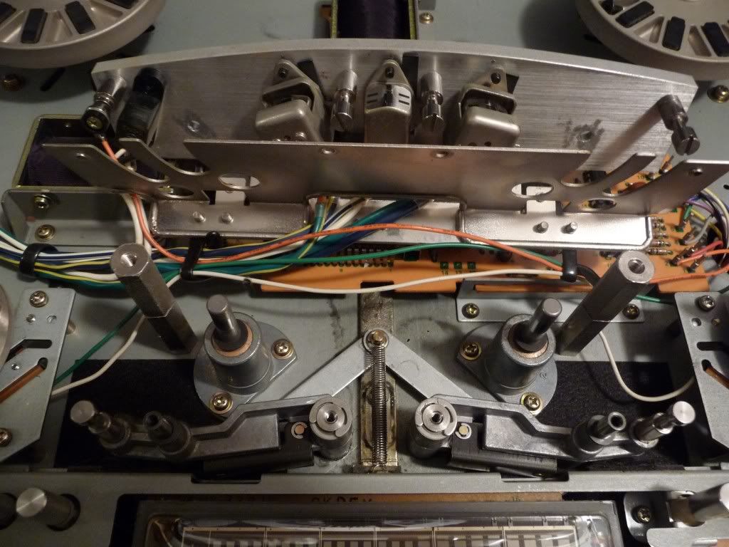
The two pinch roller arms that must be removed to clean them.
To remove these pinch roller arms is needed to remove the spring of the join, the circlip down it and each circlip of each pinch roller arm. This is the hardest part of the repair job, so be careful.
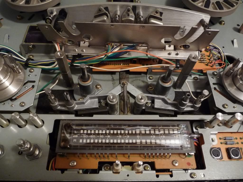
After removing the main circlips .
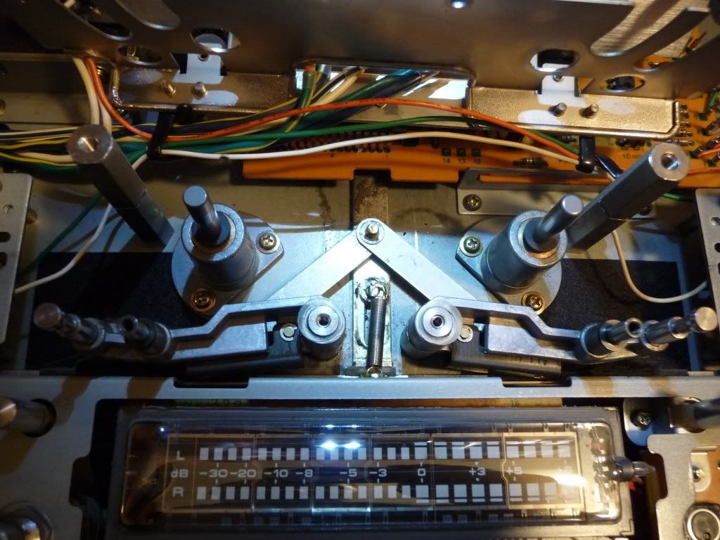
After removing the spring from the top part where is glued.
Once both pinch roller arms are free, now they can be removed.
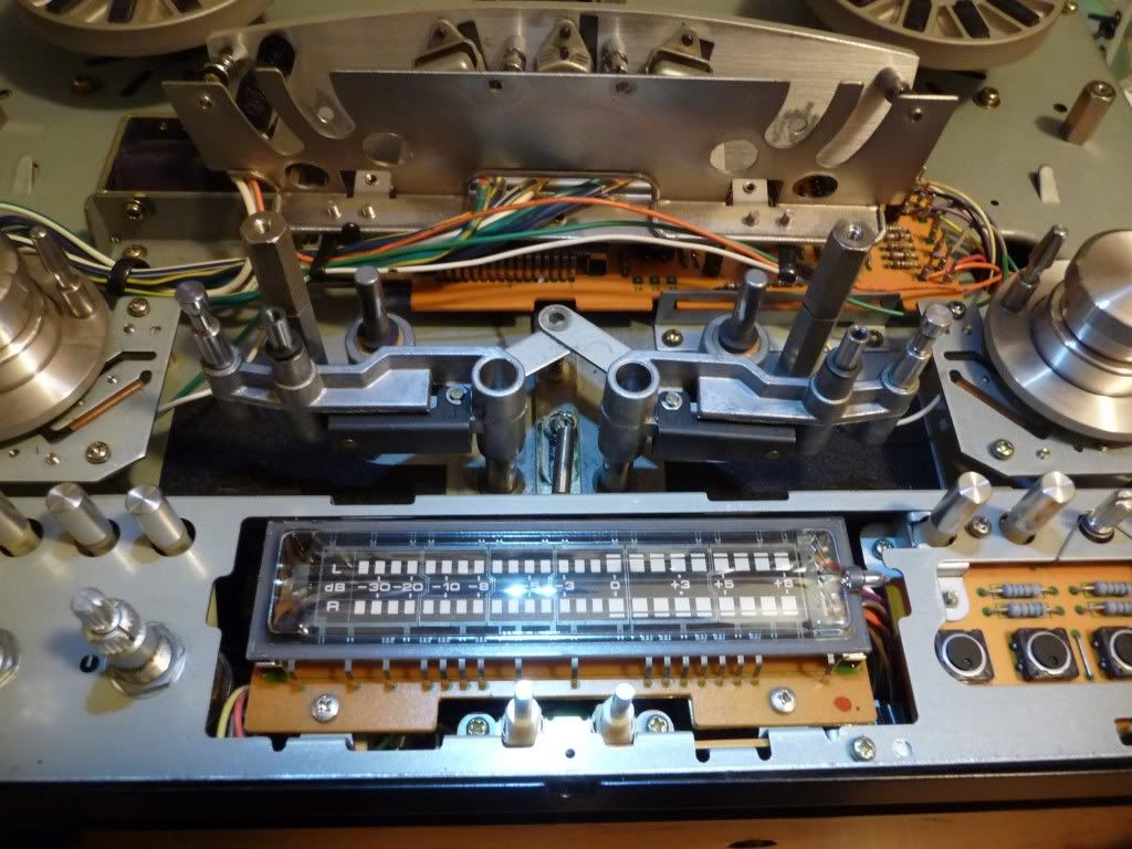
Removing the pinch roller arms.
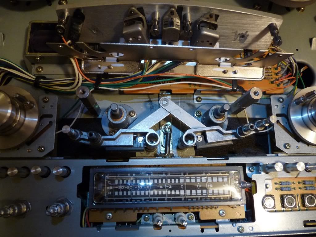
The pinch roller arms watched from the top while removing them.
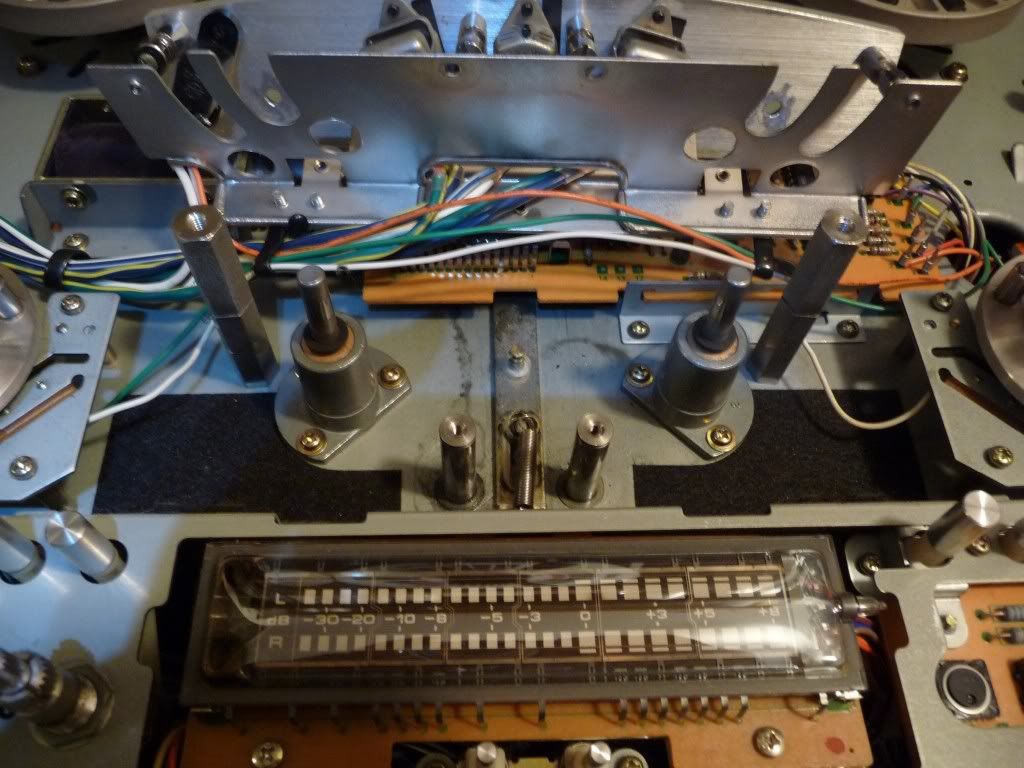
Aspect of the chasis once both pinch roller arms have been removed.
I cleaned both the inner part of them and the axis of the chasis where they were placed. All there is full of grease in bad state, so after removed it I put new grease in those zones using a cotton swab.
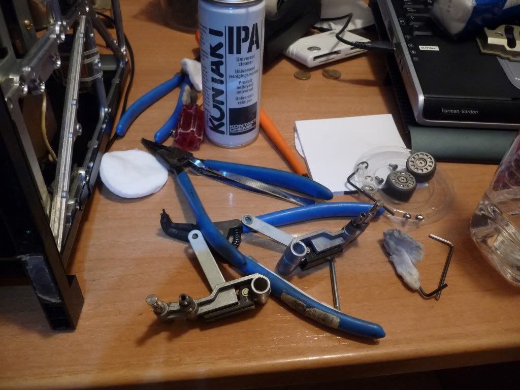
The pinch roller arms in the bench and some of the tools used in the process.
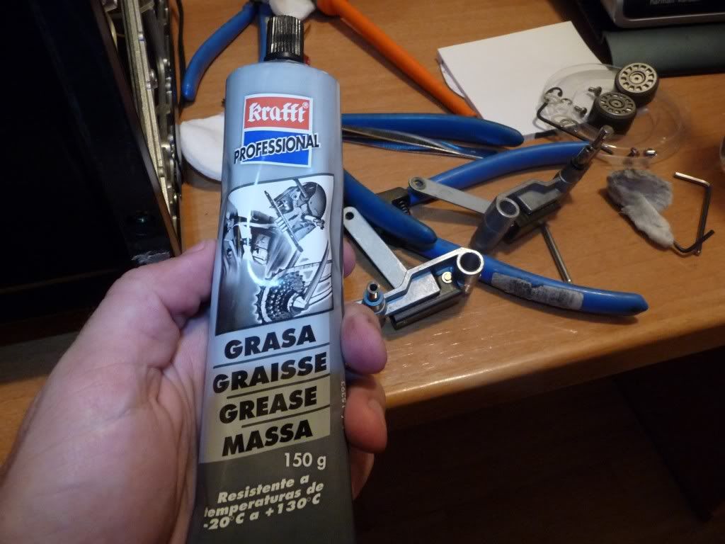
New grease that will be used to lubricate the moving parts.
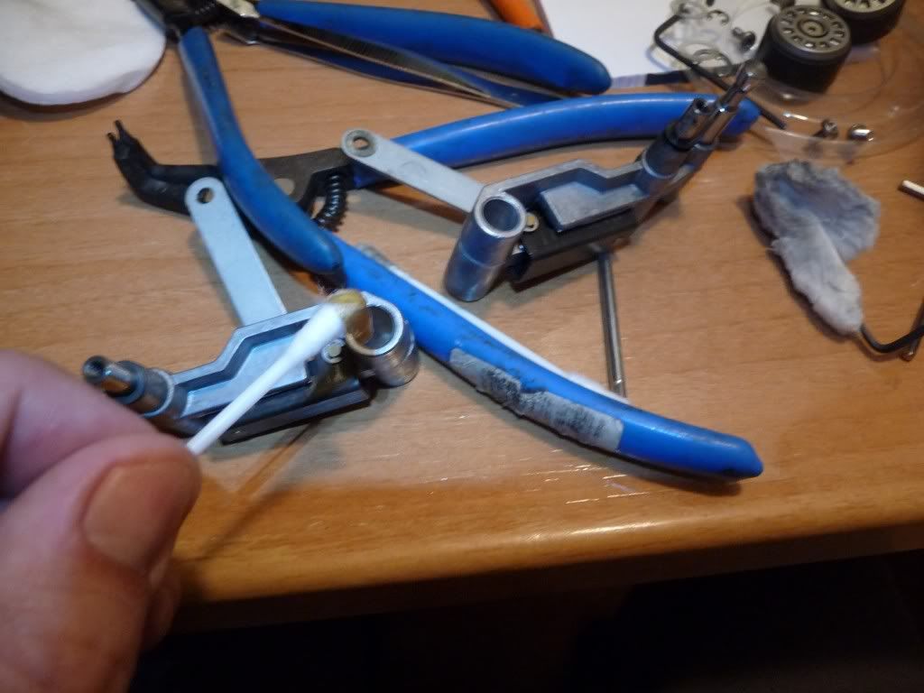
Applying new grease to the inner part of the pinch roller arms.
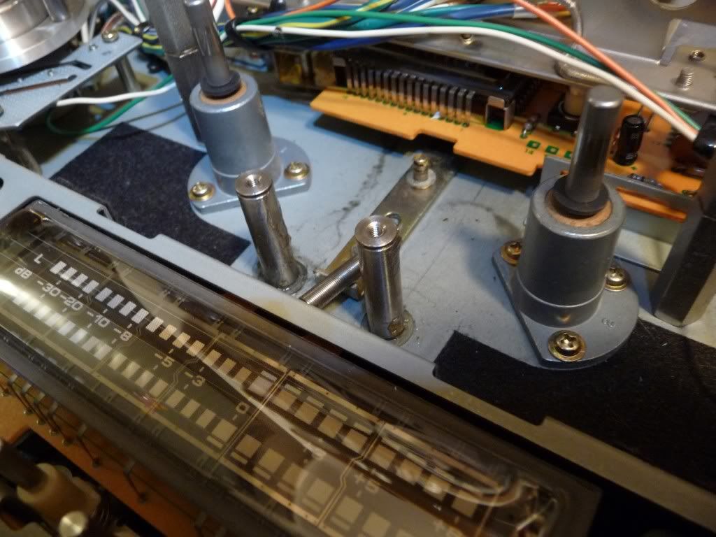
New grease put in the axis of the pinch roller arms.
Now is time to come back from the previous steps to mount all again. After put both pinch roller arms and place the spring in its original place, I glued it again so that it gets secure there.
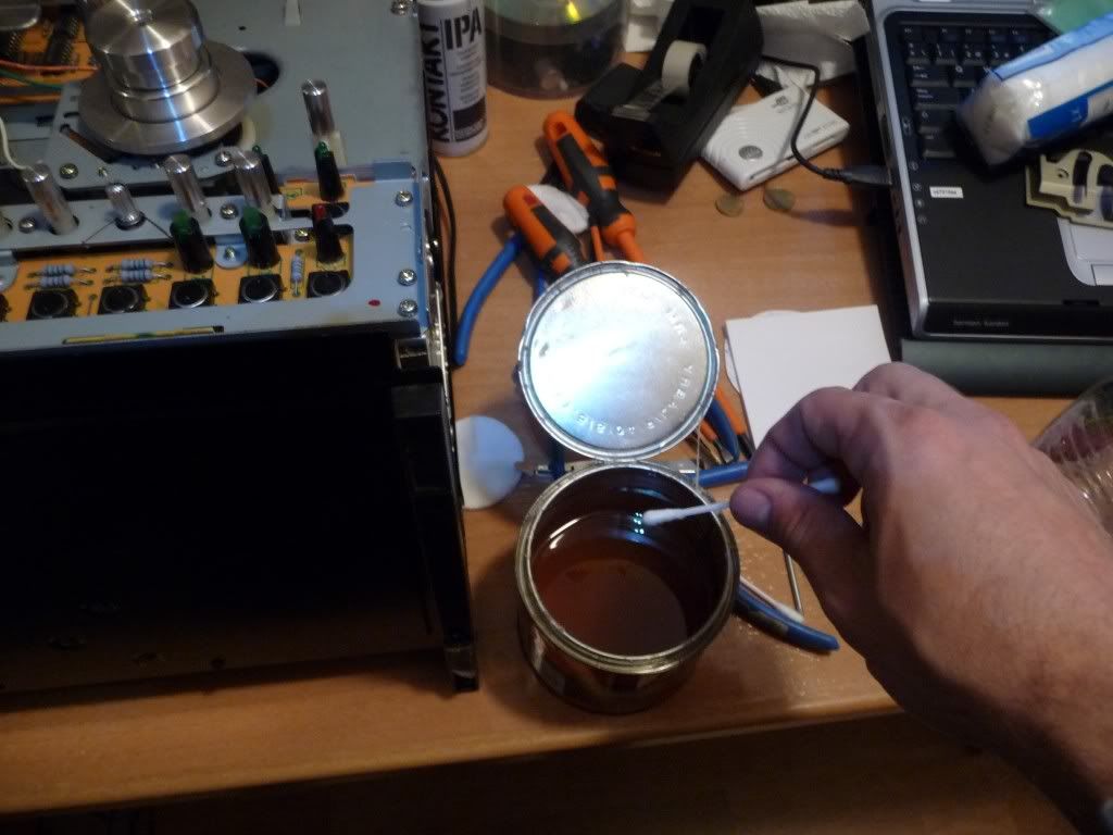
Soaking a cotton swab in glue.
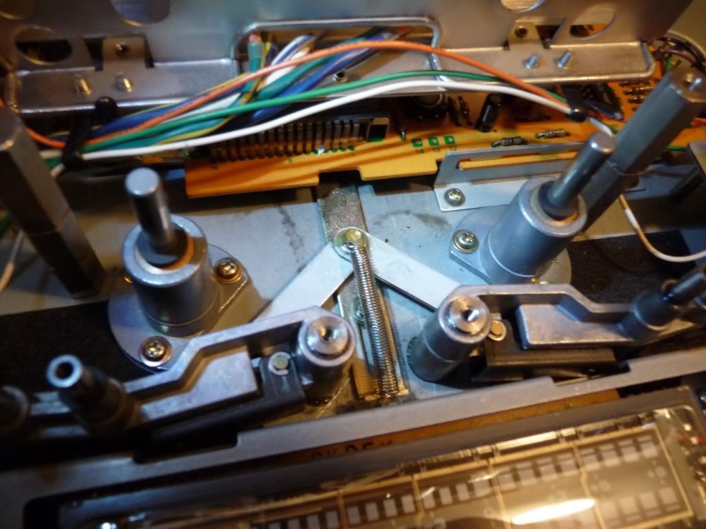
Before putting back the main circlips and after glue the spring.
After mounting the pinch roller arms, I tested the result.
Being useful that was everything disassembled, I cleaned the panels and the buttons covers using an aluminium cleaner.
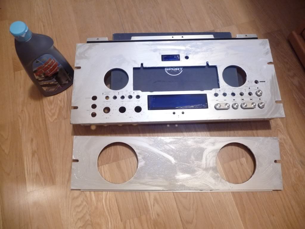
Cleaning the front panels.
To put the lower panel in its original place isn't as easy as you can think in a first watch, so take it easy and don't force anything, it must be put in its right place and no force is needed.
Mounting the panels.
Here is a video showing the final result:
To solve this problem is needed to do some work inside the machine, isn't too complicated, but are needed some tools to open class E circlips (retaining rings / E-clips).
First of all I removed eight philips screws, four per side, to remove the black cover. The top front panel has three philips screws in the top of it. Once they are removed, the top front panel can be removed pulling it from the top against you.
To remove the lower front panel is better to place the deck horizontally. Take care with the back panel because there are the input and output cinch connectors and the voltage selector (not present in all units, only in global models).
With the deck horizontally I removed three philips screws in the bottom and another three in the top of the panel. Next step is to remove the buttons covers from output volume, mic input, line input and pinch control. Is better to remove also the pinch rollers taking care not to lose all washers and screws. Before remove the bottom panel, look carefully how is mounted in the bottom part.
Both front panels and the head block removed .
With both front panels removed I went on with the head cover. Is needed an allen screwdriver to remove the two biggest screws in the head cover (they are black). I think that now all the head block can be moved just pulling it carefully, however I prefered to remove also the screws that fix the bottom thin piece that is linked to the head block.
The pieces that are directly responsible of the problem are the two arms where are mounted the pinch rollers. Both arms come together in an unique branch that is attached by a thin deck to the pinch roller solenoid. Each of those arms is mounted over a cylindrical axis and the grease between the axis and the pinch roller arm is solidified.
The two pinch roller arms that must be removed to clean them.
To remove these pinch roller arms is needed to remove the spring of the join, the circlip down it and each circlip of each pinch roller arm. This is the hardest part of the repair job, so be careful.
After removing the main circlips .
After removing the spring from the top part where is glued.
Once both pinch roller arms are free, now they can be removed.
Removing the pinch roller arms.
The pinch roller arms watched from the top while removing them.
Aspect of the chasis once both pinch roller arms have been removed.
I cleaned both the inner part of them and the axis of the chasis where they were placed. All there is full of grease in bad state, so after removed it I put new grease in those zones using a cotton swab.
The pinch roller arms in the bench and some of the tools used in the process.
New grease that will be used to lubricate the moving parts.
Applying new grease to the inner part of the pinch roller arms.
New grease put in the axis of the pinch roller arms.
Now is time to come back from the previous steps to mount all again. After put both pinch roller arms and place the spring in its original place, I glued it again so that it gets secure there.
Soaking a cotton swab in glue.
Before putting back the main circlips and after glue the spring.
After mounting the pinch roller arms, I tested the result.
Being useful that was everything disassembled, I cleaned the panels and the buttons covers using an aluminium cleaner.
Cleaning the front panels.
To put the lower panel in its original place isn't as easy as you can think in a first watch, so take it easy and don't force anything, it must be put in its right place and no force is needed.
Mounting the panels.
Here is a video showing the final result:
Saturday, March 14, 2009

MOV: Blow Out
Release date: July 1981
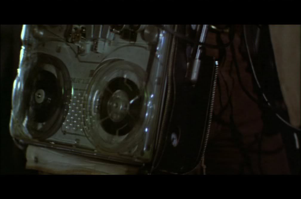
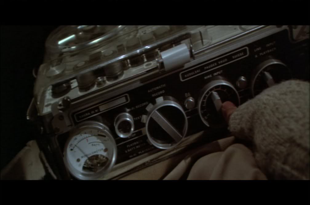

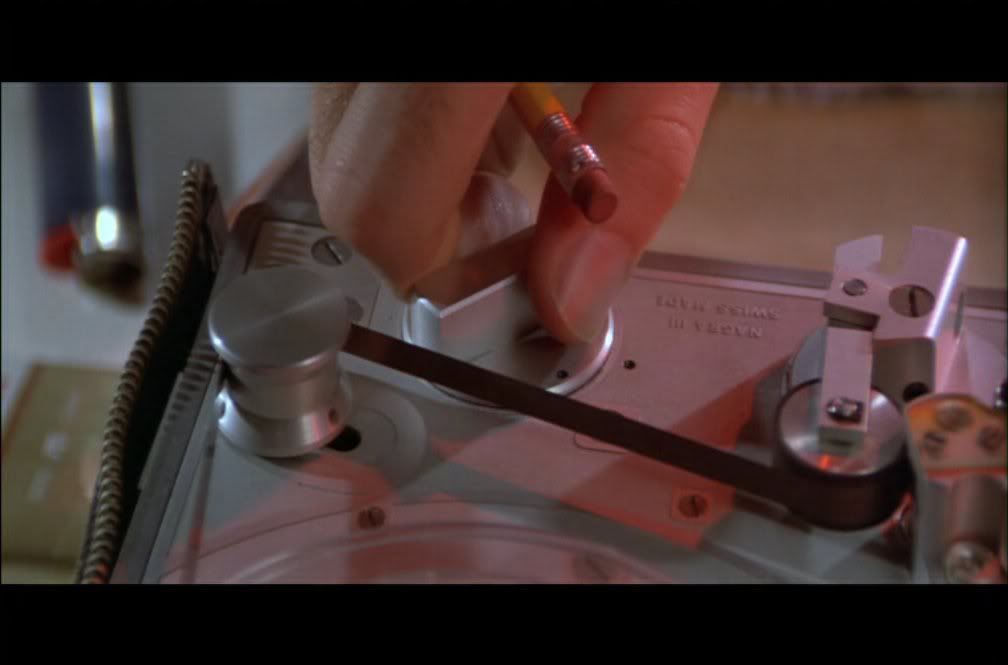
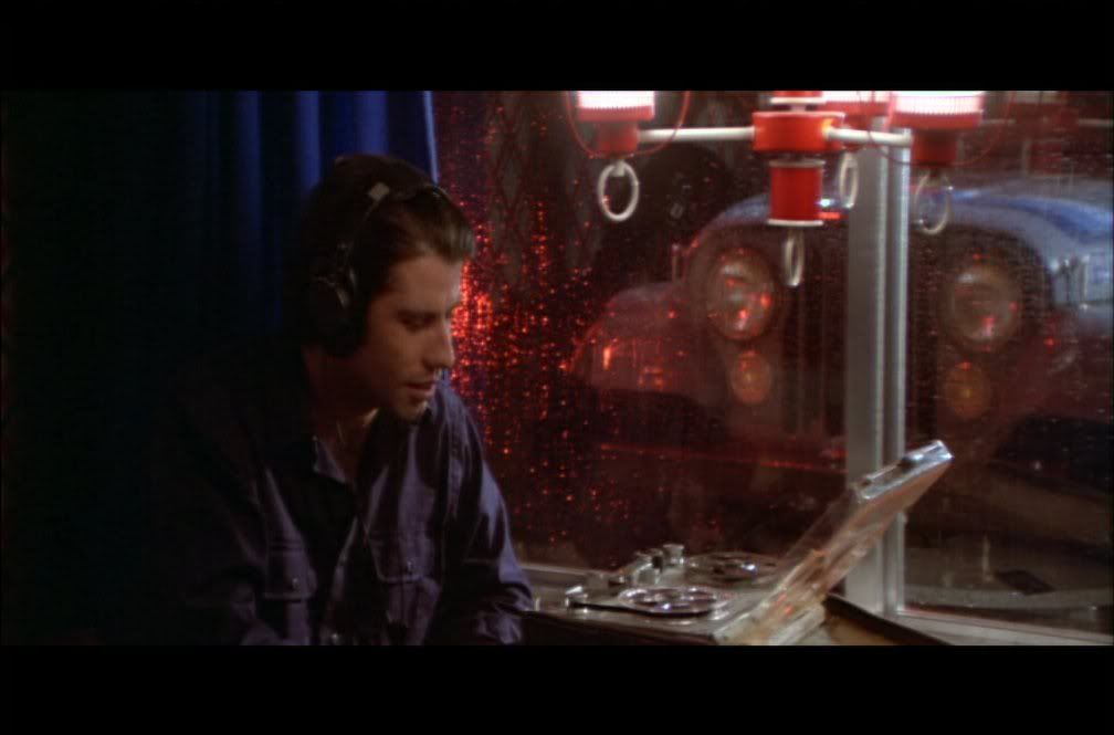
Nagra III
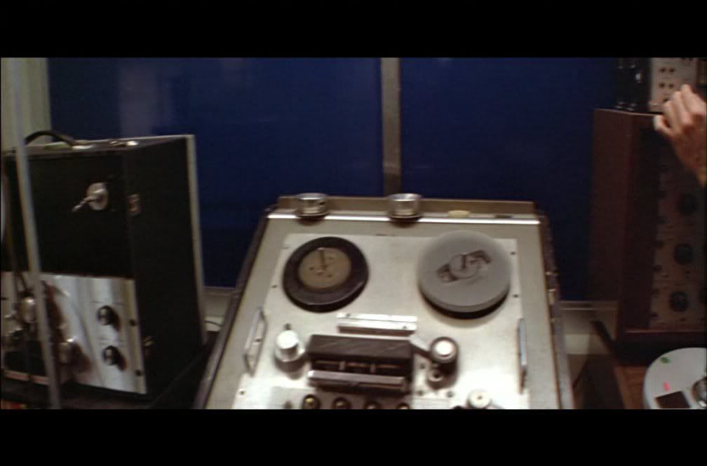
Ampex 350

Pioneer RT-2022

Ampex 350
Nagra III

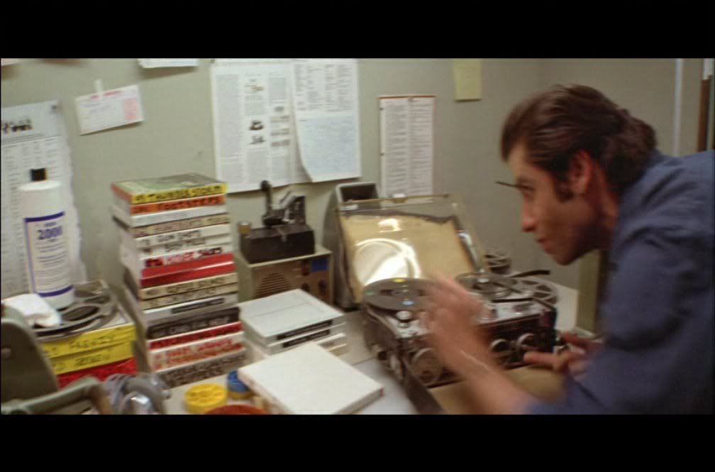
Ampex 350, Pioneer RT-2022, Scully 280B
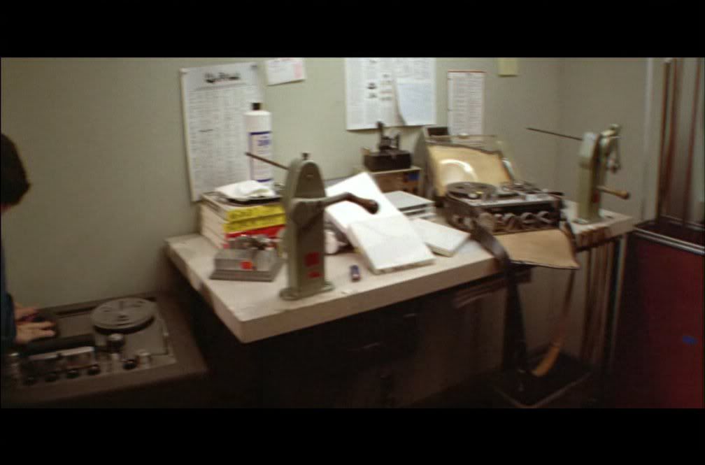
Ampex 350, Nagra III

Ampex 350, Pioneer RT-2022, Scully 280B
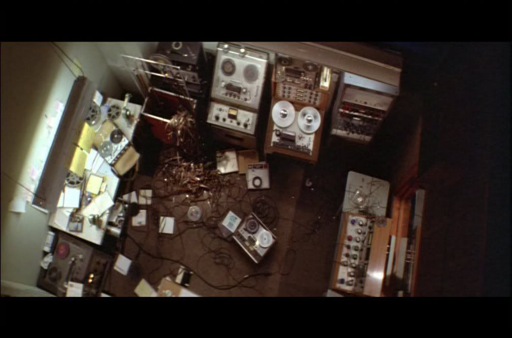
Ampex 350 (2 units), Nagra III, Pioneer RT-2022, Scully 280B
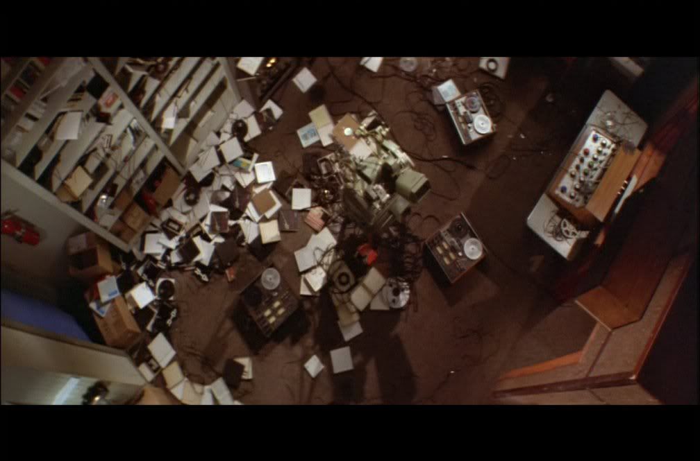
Teac 2340 (2 units), Teac 2300SR
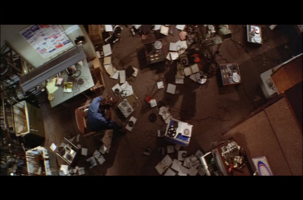
Teac 2340 (2 units), Teac 2300SR, Nagra III, ???

Nagra SN
Internet Movie Database Link
Nagra III
Ampex 350
Pioneer RT-2022
Ampex 350
Nagra III
Ampex 350, Pioneer RT-2022, Scully 280B
Ampex 350, Nagra III
Ampex 350, Pioneer RT-2022, Scully 280B
Ampex 350 (2 units), Nagra III, Pioneer RT-2022, Scully 280B
Teac 2340 (2 units), Teac 2300SR
Teac 2340 (2 units), Teac 2300SR, Nagra III, ???
Nagra SN
Internet Movie Database Link
Subscribe to:
Posts (Atom)


 Posts
Posts

